
Precision Mold Insert CAD Drawing Standards
The mold insert is the core forming component of injection molds. The precision of CAD dimensioning for 2D machining drawings directly governs the qualification rate of CNC and EDM machining, as well as the mass production stability of molds. For European and American export mold design, overseas clients impose strict requirements on drawing standardization, tolerance accuracy and unified machining benchmarks. We conduct standardized CAD dimensioning in full compliance with mainstream European and American mold standards including HASCO and DME. Adopting AutoCAD and ZWCAD software platforms, we deliver complete standardized precision mold drawings that fully adapt to the machining habits and inspection standards of European and American mold manufacturers. Taking a precision automotive sensor export mold insert as a practical case, this article elaborates on the standardized CAD dimensioning procedures and process specifications for European and American precision mold design. For complete Western-style mold design solutions, please visit our overseas official website: Western Precision Mold Design.
1. Basic CAD Design Parameters for European & American Export Molds
- Mold Insert Specification: Premium hardened mold insert for European and American automotive sensor exports, with overall quenching and hardening treatment to meet long-term high-precision mass production requirements of Western high-end injection products.
- Design Platform: Adopt AutoCAD and ZWCAD professional design software, unify drawing dimensioning specifications compliant with European and American mold industry standards, ensuring full compatibility with overseas processing equipment reading standards.
- Machining Reference: Adopt a single-origin unified dimensioning method. All dimensional standards are completely consistent with CNC programming and EDM machining specifications adopted by European and American mold processing factories.
2. Four Core CAD Dimensioning Standards for Western Precision Molds
1. Standardized Reference Dimensioning for Mold Insert Layout
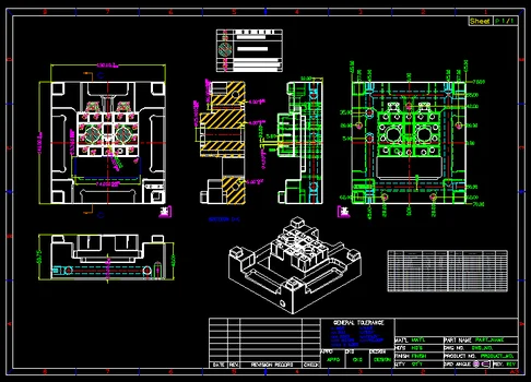
The 2D general layout drawing of mold inserts is the core basis for mold manufacturing. We uniformly mark the outline dimension, parting line, reference corner and machining origin, with standardized fonts, arrows and line styles. It enables barrier-free drawing reading for European and American engineers and processing teams, realizing complete synchronization of design and machining data.
2. Graded High-Precision Tolerance Design
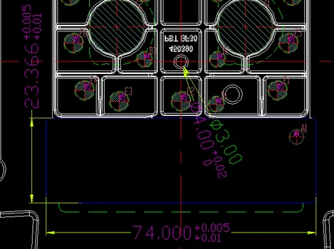
Following Western mold tolerance systems, we apply strict tolerances for sealing, inserting and fitting positions, and reasonably relax tolerances for non-fitting appearance areas. This effectively solves mass production defects such as flashing and assembly gaps, balances mold precision and manufacturing costs, and conforms to Western mass production mold design concepts.
3. Standard Component Specification Statistics List
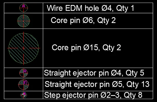
The automatically generated ejector pin and sleeve specification statistic table strictly matches HASCO and DME Western standard parts specifications. Equipped with complete English BOM documents, it facilitates overseas customers’ parts procurement, mold assembly and quality inspection acceptance.
4. High-Precision Hole Position Coordinate Output
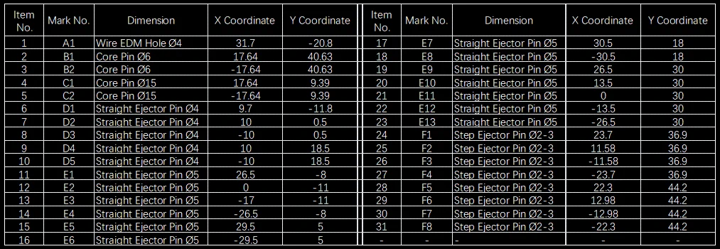
All ejector pin holes and sleeve holes are dimensioned with independent benchmark coordinates based on a unified origin. The data can be directly imported into CAM programming software, completely avoiding cumulative errors caused by chain dimensioning. It greatly improves the machining and assembly accuracy of multi-hole precision mold inserts, adapting to Western automated injection molding production lines.
3. Key CAD Dimensioning Specifications for Western Export Molds
- Unified Benchmark Origin: The CAD dimensioning origin is strictly consistent with the CNC programming origin to eliminate machining dislocation and assembly deviation.
- Heat Treatment Process Marking: Clearly mark the machining sequence for hardened mold inserts to prevent tool damage and mold deformation caused by drilling after quenching.
- Dual Data Verification Mechanism: Output both quantity statistic tables and coordinate tables simultaneously to unify data standards for machining, quality inspection and assembly.
- Western-Style Drawing Standard: Adopt unified Western mold drawing styles and specifications to ensure consistent drawing presentation during multi-person collaboration, meeting overseas mold acceptance standards.